
PXLtools — Tool guide
Camera Matchmaker — single-image camera match
Load a still photo onto the canvas, draw axis lines along real-world parallel edges, set the origin, and Camera Matchmaker solves the camera — Horizontal FOV, Pan, Tilt, Roll — from the vanishing points. One click applies the result to a Maya camera with an image plane attached. A three-step gated flow walks you from canvas setup through scene data to output.
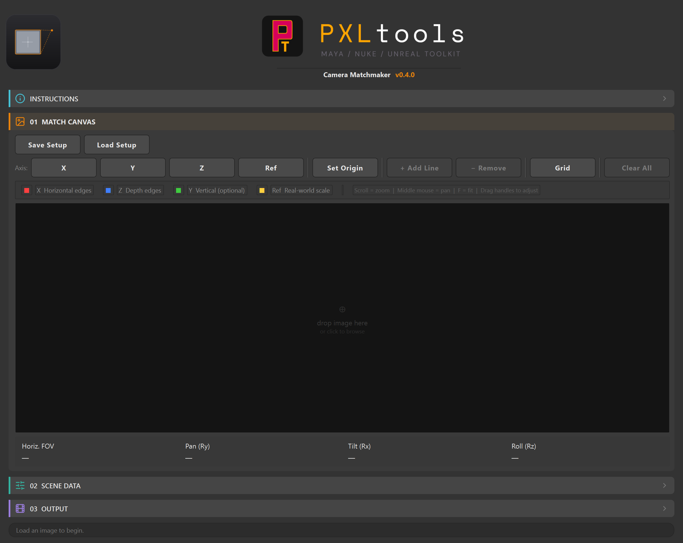
The interface
01
Overview
Early prototype — under active development. Camera Matchmaker v0.3.0-alpha is an early prototype. The UI shown here and the solver behaviour may change between versions. Test on non-critical shots before integrating into a production pipeline.
Camera Matchmaker is an interactive single-image camera matching tool for Maya, inspired by fSpy. Load a reference photograph onto the canvas, draw axis lines along edges you know to be parallel in the real world, set the scene origin, and the tool solves the camera using a weighted least-squares vanishing point algorithm (Guillou et al., 2000).
The solve reads out Horizontal FOV, Pan (Ry), Tilt (Rx), and Roll (Rz) live as you adjust the lines. When you are happy with the result, one click creates a new Maya camera (or applies to an existing one) with the solved values and attaches the reference image as an image plane. It shares the same UI kit as the rest of PXLtools.
02
Requirements
- Autodesk Maya 2025
- Python 3.11 (included with Maya 2025)
Tested on:
- Autodesk Maya 2025
Newer releases generally work, but these are the versions every release is actually tested against. If something behaves oddly on a newer host, that is worth reporting.
Network access
PXLtools needs outbound HTTPS (TCP 443) to www.pxlmentor.com and
objects.githubusercontent.com for licensing and updates. On a studio or corporate
machine, check this before you install — see
Troubleshooting.
Maya 2025 already includes PySide6. You do not install it, you do not pip anything, you do not touch your Python environment.
03
Availability
Camera Matchmaker is a prototype. It runs here on real shots, but it is not finished and is not available to download — on the site and on the store it is shown greyed out for exactly that reason. The tools that are ready are free: see them on the store.
04
Using Camera Matchmaker
The tool has three collapsible sections: 01 MATCH CANVAS, 02 SCENE DATA, and 03 OUTPUT. Work through them in order.
The step flow
Each numbered section is independent but designed to be completed in sequence. The solve updates live as you draw and adjust lines, so you can see the FOV and rotation values before committing to a camera.
Canvas shortcuts
Scroll — zoom
Scroll the mouse wheel to zoom in and out on the canvas.
Middle mouse — pan
Hold and drag the middle mouse button to pan around the canvas.
F — fit / drag handles — adjust lines
Press F to fit the image back to the viewport. Drag the coloured endpoint handles to reposition any line.
01 MATCH CANVAS
Load your reference image and draw the axis lines that define the vanishing points.
- Load an image. Click the canvas drop zone (or drag and drop an image file onto it) to load your reference photograph. Supported formats: JPG, PNG, TIF, BMP, EXR, HDR.
- Draw X Axis lines (red). Select
Xin the axis toolbar and click+ Add Line, then click and drag on the canvas to draw a line along a horizontal parallel edge — e.g. a floor edge, window sill, or ceiling cornice going sideways. Add at least 2 lines. The vanishing point is computed live and shown as a red marker. - Draw Z Axis lines (blue). Select
Zand add at least 2 lines along depth-parallel edges — edges that go away into the scene. The solver needs both X and Z vanishing points to compute the camera. - Optional: Y Axis lines (green). Select
Yand add lines along vertical reference edges (columns, door frames) to constrain the vertical vanishing point. - Optional: Ref line (yellow). Select
Refand draw across a known real-world object to set scene scale for the position solve. Configure the real-world size in02 SCENE DATA. - Set the Origin. Click
Set Originand click on the canvas to place the scene world origin (0, 0, 0) marker. Used for the camera position estimation. - Read the solve. The readout below the canvas shows Horiz. FOV, Pan (Ry), Tilt (Rx), and Roll (Rz) as soon as the solver has enough lines.
02 SCENE DATA
Optional ground-truth constraints for the position solve.
- Camera Height. Real-world height of the camera lens above the ground plane. Enabled by default at a sensible default for your Maya scene unit. Required for position estimation — uncheck if unknown.
- Camera Lens. Override the computed focal length with a known lens value (assumes 36 mm full-frame sensor). Leave off to derive from vanishing points.
- Measurement Ref. If you drew a
Refline in the canvas, enable this and enter the real-world size of the object the line crosses. This scales the position solve.
03 OUTPUT
Apply the solved camera to Maya.
- CREATE NEW CAMERA. Creates a new Maya camera named
MatchCam_01(editable) with the solved FOV and rotation, and optionally attaches the reference image as an image plane. - APPLY TO CAMERA. Applies the solve to an existing camera you select from the dropdown. Choose which of FOV, Rotation, and Position to set.
- ADD IMAGE PLANE. Attaches the loaded reference image to the selected camera without changing its transform.
Tip: After applying, use Place Test Object at Origin in the Verify tab of the OUTPUT section to place a reference cube at (0, 0, 0) and look through the solved camera to check alignment against the photo.
05
Troubleshooting
The install fails, or the tool says it cannot reach pxlmentor.com.
This is a firewall almost every time, not a broken installer — and it is very common on studio and corporate machines. PXLtools needs outbound HTTPS on TCP 443 to two hosts:
Send this to your IT team
www.pxlmentor.com  (TCP 443) — licence checks, update checks, downloads
objects.githubusercontent.com  (TCP 443) — the actual file download
Both hosts, not just the first. The download is handed off to a signed link on
objects.githubusercontent.com, so a rule that allows pxlmentor.com but
blocks the second host lets the version check succeed and then fails the download.
A certificate error instead means your network is inspecting HTTPS traffic (Zscaler, Netskope, a corporate SSL appliance) — that needs an SSL-inspection exception for those hosts, not a port opening.
The installer writes full details to ~/Documents/PXLtools/install_failure.log. Email it to
support@pxlmentor.com
and I will tell you which case it is. If your IT will not budge, ask for the offline package.
The + Add Line button is disabled.
Load an image onto the canvas first. The axis toolbar is inactive until a reference image is loaded.
The solve readout shows “—” for FOV and rotation.
The solver requires at least 2 X Axis lines and 2 Z Axis lines to compute a result. Draw both sets of lines and the readout updates automatically.
The Ref line sets scale but the position looks wrong.
Enable Measurement Ref in section 02 SCENE DATA and enter the correct real-world size of the object the yellow Ref line crosses. The Ref line drawn on canvas only registers as scale data when this checkbox is ticked and a value is set.
CREATE NEW CAMERA and APPLY TO CAMERA are greyed out.
The output buttons activate only after a valid solve is available. Draw the minimum required X and Z axis lines until the solve readout shows real numbers, then the buttons become clickable.